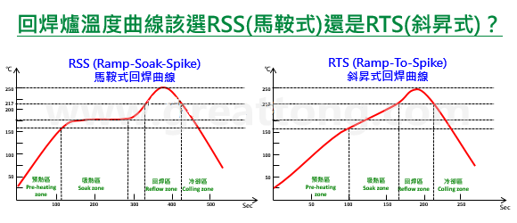
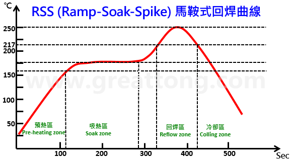
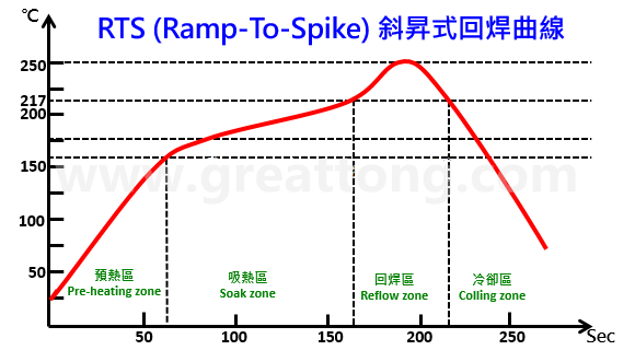
PCBA Lecture Hall: Should RSS be used for the furnace temperature curve of reflow soldering? Or RTS type?


Should the Reflow temperature profile be set to RSS (saddle type)? Or should it be set to RTS type (ramp-up type)? TESDATA FOUND THAT MANY PCBA ENGINEERS HAVE BEEN TROUBLED BY THIS PROBLEM, BECAUSE SOME BOSSES ASKED TO TAKE RTS, BUT THEY WERE AFRAID OF IT. Actually, there is no difficulty in answering this question, but you must first understand what "RSS" and "RTS" temperature curves are, and only after understanding the purpose and limitations of their curve settings can you choose a reflow temperature profile that meets your product. In this article, TESDATA tries to sort out the characteristics of the two types of reflow soldering temperature curves, "RSS type" and "RTS type", and the problems they are currently encountering, and provide a direction to choose. TESDATA doesn't dare to say that the following are the most correct, but put forward personal opinions for your reference, please think twice before adopting. RSS:Ramp-Soak-Spike Heating-Endothermy-Reflow Some people translate the "Soak zone" in the reflow curve as "constant temperature zone" and some people translate it as "infiltration zone", but Mr. Bai suggests that it should be translated as "endothermic zone" or "active zone". As the name suggests, the temperature curve is that there will be a flat constant temperature area, because the temperature curve is drawn like a "saddle" (a flat place can sit on a person), so the "RSS type" reflow temperature curve is also called "saddle type". RSS (Ramp-Soak-Spike) The main purpose of this constant temperature zone setting before resoldering is to make all the solder pads/pads on the surface of the PCB connected with a large area of grounded copper foil and a small area of copper foil ungrounded, and so that the temperature of components and solder legs of different sizes and textures can reach the same temperature before entering the reflow area, and the best soldering effect can be achieved during resoldering, which is why Mr. Bai suggested that this area be called the "endothermic zone". Let all objects that want to enter the reflow solder absorb the heat to a consistent temperature. It's like waiting for a while before marching to battle, gathering all the scattered soldiers together, and then charging forward in one go, which is a bit similar, otherwise everyone will be easily broken by each piece. If the temperature of SMD components is uneven (the "temperature difference △T" is too large), it is easy to have the disadvantages of soldering: ▪ If the temperature of SMD components is inconsistent when entering the reflow area, it is easy to have parts that are not soldered in place (insufficient temperature) or parts that are scalded and melted (the temperature is too high or the temperature is too long). ▪ If the PCB pad/pad of the same part cannot reach the same temperature before entering the reflow zone, it is prone to tombstone effect, and BGA is prone to HoP/HiP or NWO disadvantages. ▪ If the solder pads/pads of the part and the corresponding pads cannot reach the same temperature before entering the reflow zone, it is easy to have the disadvantage that all the solder will crawl to the solder feet (siphon phenomenon) or the solder feet will not stick to the tin. In the current SAC305 lead-free solder paste resoldering process, the temperature of this constant temperature zone is usually maintained in the range of 150±10°C, and this temperature is basically maintained on the eve of the solder paste melting, on the one hand, waiting for the large army to assemble (so that the temperature tends to be consistent), on the other hand, the flux in the solder paste will begin to play the role of removing oxides. However, it should be noted that at the temperature of this constant temperature zone, the solvent originally added to the flux of the solder paste will also begin to accelerate volatilization due to the increase in temperature, although the activator will also start and begin to remove the oxide on the surface of the solder, but the best time to remove the oxide should be when the solder paste has just begun to melt, because the melted solder paste can be pushed and removed by liquid tin to the edge or outside of the entire solder, so that there will be no oxide residue when the solder is formed and cause solder defects. Therefore, according to the characteristics of the solder paste flux, theoretically, the temperature of this constant temperature zone should not be too high or too long, otherwise the flux will dry up quickly, which is not conducive to the performance of the flux when the solder is melted, because the amount of flux residue when entering the reflux area will be directly related to the quality of the soldering~ This is the key point that many PCBA engineers ignore. For this reason, all solder paste manufacturers should tell you that the temperature of the constant temperature zone should not be set too high, let alone too long, and the heating slope after the constant temperature zone should not be too low, and it is not recommended to be lower than 1 °C/Sec, the purpose is to retain the most flux into the reflow area, if the flux is greatly reduced before entering the refill, the shortcomings of air soldering (non-wetting), cold soldering (De-wetting) and HoP/HiP or NWO will be greatly increased. However, if the slope of the secondary heating is too fast, the problem of "tin splashing" will occur, imagine the situation when the pan is frying the fish too large and the fish is put into the oil pan, appropriately reducing the slope of the secondary heating will help reduce the "tin splash". Therefore, the setting of the slope is simply a narrow door. In principle, it is not recommended to exceed 3 °C/Sec, because there is rosin in the flux of solder paste, and its softening point is about 90 °C ~ 110 °C short)。 RTS: Ramp-To-Spike Heating directly to reflow, eliminating the need for a constant temperature zone RTS type reflow curve is also known as "hill type" or "ramp type". RSS (Ramp-Soak-Spike) Saddle Reflow Curve As mentioned in the previous article, so many RSS constant temperature zones prevent fluxes from achieving optimal soldering results. Therefore, the main purpose of this RTS type reflux curve is to meet the characteristics of the flux as the premise of the design of the temperature return curve, since the RSS constant temperature zone will make the flux accelerate volatilization and drying, then do not want this constant temperature zone, or change this constant temperature zone to a slow heating zone, which can not only greatly reduce the rate of flux volatilization, improve the flux residue rate during resoldering, but also improve the solderability of resoldering (if you can't understand this paragraph, Please go back to the article and revisit the characteristics of the RSS type reflow curve), and it can also shorten the time of the entire reflow through the furnace, which is equivalent to achieving the effect of saving energy, why not? However, the elimination of the "constant temperature zone" means that the "temperature difference △T" may increase, so as long as all the pads/pads on the board and the solder legs of all parts are controlled not to be too high before entering the recycle temperature, this RTS-type reflow curve should be used. Which PCBA boards are suitable for RTS reflow curve? With the development of science and technology, more and more reflow ovens now have the ability to compensate for efficient thermal energy, especially those reflow ovens with more than 10 temperature zones, which will no longer have the problem of high and low drift of temperature because of the density of the board in the reflow furnace, which is very helpful for the use of RTS in the reflow furnace, because there is a very important limitation when designing RSS, that is, the thermal efficiency of the reflow furnace cannot keep up. Therefore, having a reflow oven with high efficiency thermal compensation is an important condition for the use of RTS. RTS (Ramp-To-Spike) Ramp-To-Spike Reflow Curve Compromise Again, if the parts on your PCBA are very simple, without too many complex parts, such as BGA or large parts that are particularly easy or not easy to absorb heat, that is to say, the temperature between the parts can easily reach uniformity, it is recommended to use "RTS ramp-to-spike". However, if your board is too large or has too many layers, even if the parts are simple, it is recommended to measure whether the temperature of each key position can be consistent before entering the reflow area through the temperature measuring plate. After confirming that it is feasible, first try run a small amount to ensure that the solder defects are within the controllable range, and then produce in large quantities, and observe a few batches of no problems before you can really rest assured that the production line can change the reflow curve to RTS. The reason is that most of the plate spacing in the reflow furnace is loose during the test run, but the board spacing is shortened after a large number of productions, coupled with the insufficient energy supply of the reproduction furnace, so the phenomenon of non-tin is caused, especially the soldering pads/pads connected with a large area of grounded copper foil are more serious. Now you should know that your reflow temperature profile should be set to RSS? Or set it to RTS type~
 
Should the Reflow temperature profile be set to RSS (saddle type)? Or should it be set to RTS type (ramp-up type)? TESDATA FOUND THAT MANY PCBA ENGINEERS HAVE BEEN TROUBLED BY THIS PROBLEM, BECAUSE SOME BOSSES ASKED TO TAKE RTS, BUT THEY WERE AFRAID OF IT.
 
Actually, there is no difficulty in answering this question, but you must first understand what "RSS" and "RTS" temperature curves are, and only after understanding the purpose and limitations of their curve settings can you choose a reflow temperature profile that meets your product.
 
In this article, TESDATA tries to sort out the characteristics of the two types of reflow soldering temperature curves, "RSS type" and "RTS type", and the problems they are currently encountering, and provide a direction to choose. TESDATA doesn't dare to say that the following are the most correct, but put forward personal opinions for your reference, please think twice before adopting.
 
RSS: Ramp-Soak-Spike Heat Up-Endothermy-Reflow
The "Soak zone" in the reflow curve is translated as "constant temperature zone" and some people translate it as "infiltration zone", but Mr. Bai suggests that it should be translated as "endothermic zone" or "active zone". As the name suggests, the temperature curve is that there will be a flat constant temperature area, because the temperature curve is drawn like a "saddle" (a flat place can sit on a person), so the "RSS type" reflow temperature curve is also called "saddle type".
 
Should the Reflow temperature profile be set to RSS (saddle type)? Or should it be set to RTS type (ramp-up type)? TESDATA FOUND THAT MANY PCBA ENGINEERS HAVE BEEN TROUBLED BY THIS PROBLEM, BECAUSE SOME BOSSES ASKED TO TAKE RTS, BUT THEY WERE AFRAID OF IT. Actually, there is no difficulty in answering this question, but you must first understand what "RSS" and "RTS" temperature curves are, and only after understanding the purpose and limitations of their curve settings can you choose a reflow temperature profile that meets your product. In this article, TESDATA tries to sort out the characteristics of the two types of reflow soldering temperature curves, "RSS type" and "RTS type", and the problems they are currently encountering, and provide a direction to choose. TESDATA doesn't dare to say that the following are the most correct, but put forward personal opinions for your reference, please think twice before adopting. RSS:Ramp-Soak-Spike Heating-Endothermy-Reflow Some people translate the "Soak zone" in the reflow curve as "constant temperature zone" and some people translate it as "infiltration zone", but Mr. Bai suggests that it should be translated as "endothermic zone" or "active zone". As the name suggests, the temperature curve is that there will be a flat constant temperature area, because the temperature curve is drawn like a "saddle" (a flat place can sit on a person), so the "RSS type" reflow temperature curve is also called "saddle type". RSS (Ramp-Soak-Spike) The main purpose of this constant temperature zone setting before resoldering is to make all the solder pads/pads on the surface of the PCB connected with a large area of grounded copper foil and a small area of copper foil ungrounded, and so that the temperature of components and solder legs of different sizes and textures can reach the same temperature before entering the reflow area, and the best soldering effect can be achieved during resoldering, which is why Mr. Bai suggested that this area be called the "endothermic zone". Let all objects that want to enter the reflow solder absorb the heat to a consistent temperature. It's like waiting for a while before marching to battle, gathering all the scattered soldiers together, and then charging forward in one go, which is a bit similar, otherwise everyone will be easily broken by each piece. If the temperature of SMD components is uneven (the "temperature difference △T" is too large), it is easy to have the disadvantages of soldering: ▪ If the temperature of SMD components is inconsistent when entering the reflow area, it is easy to have parts that are not soldered in place (insufficient temperature) or parts that are scalded and melted (the temperature is too high or the temperature is too long). ▪ If the PCB pad/pad of the same part cannot reach the same temperature before entering the reflow zone, it is prone to tombstone effect, and BGA is prone to HoP/HiP or NWO disadvantages. ▪ If the solder pads/pads of the part and the corresponding pads cannot reach the same temperature before entering the reflow zone, it is easy to have the disadvantage that all the solder will crawl to the solder feet (siphon phenomenon) or the solder feet will not stick to the tin. In the current SAC305 lead-free solder paste resoldering process, the temperature of this constant temperature zone is usually maintained in the range of 150±10°C, and this temperature is basically maintained on the eve of the solder paste melting, on the one hand, waiting for the large army to assemble (so that the temperature tends to be consistent), on the other hand, the flux in the solder paste will begin to play the role of removing oxides. However, it should be noted that at the temperature of this constant temperature zone, the solvent originally added to the flux of the solder paste will also begin to accelerate volatilization due to the increase in temperature, although the activator will also start and begin to remove the oxide on the surface of the solder, but the best time to remove the oxide should be when the solder paste has just begun to melt, because the melted solder paste can be pushed and removed by liquid tin to the edge or outside of the entire solder, so that there will be no oxide residue when the solder is formed and cause solder defects. Therefore, according to the characteristics of the solder paste flux, theoretically, the temperature of this constant temperature zone should not be too high or too long, otherwise the flux will dry up quickly, which is not conducive to the performance of the flux when the solder is melted, because the amount of flux residue when entering the reflux area will be directly related to the quality of the soldering~ This is the key point that many PCBA engineers ignore. For this reason, all solder paste manufacturers should tell you that the temperature of the constant temperature zone should not be set too high, let alone too long, and the heating slope after the constant temperature zone should not be too low, and it is not recommended to be lower than 1 °C/Sec, the purpose is to retain the most flux into the reflow area, if the flux is greatly reduced before entering the refill, the shortcomings of air soldering (non-wetting), cold soldering (De-wetting) and HoP/HiP or NWO will be greatly increased. However, if the slope of the secondary heating is too fast, the problem of "tin splashing" will occur, imagine the situation when the pan is frying the fish too large and the fish is put into the oil pan, appropriately reducing the slope of the secondary heating will help reduce the "tin splash". Therefore, the setting of the slope is simply a narrow door. In principle, it is not recommended to exceed 3 °C/Sec, because there is rosin in the flux of solder paste, and its softening point is about 90 °C ~ 110 °C short)。 RTS: Ramp-To-Spike Heating directly to reflow, eliminating the need for a constant temperature zone RTS type reflow curve is also known as "hill type" or "ramp type". RSS (Ramp-Soak-Spike) Saddle Reflow Curve As mentioned in the previous article, so many RSS constant temperature zones prevent fluxes from achieving optimal soldering results. Therefore, the main purpose of this RTS type reflux curve is to meet the characteristics of the flux as the premise of the design of the temperature return curve, since the RSS constant temperature zone will make the flux accelerate volatilization and drying, then do not want this constant temperature zone, or change this constant temperature zone to a slow heating zone, which can not only greatly reduce the rate of flux volatilization, improve the flux residue rate during resoldering, but also improve the solderability of resoldering (if you can't understand this paragraph, Please go back to the article and revisit the characteristics of the RSS type reflow curve), and it can also shorten the time of the entire reflow through the furnace, which is equivalent to achieving the effect of saving energy, why not? However, the elimination of the "constant temperature zone" means that the "temperature difference △T" may increase, so as long as all the pads/pads on the board and the solder legs of all parts are controlled not to be too high before entering the recycle temperature, this RTS-type reflow curve should be used. Which PCBA boards are suitable for RTS reflow curve? With the development of science and technology, more and more reflow ovens now have the ability to compensate for efficient thermal energy, especially those reflow ovens with more than 10 temperature zones, which will no longer have the problem of high and low drift of temperature because of the density of the board in the reflow furnace, which is very helpful for the use of RTS in the reflow furnace, because there is a very important limitation when designing RSS, that is, the thermal efficiency of the reflow furnace cannot keep up. Therefore, having a reflow oven with high efficiency thermal compensation is an important condition for the use of RTS. RTS (Ramp-To-Spike) Ramp-To-Spike Reflow Curve Compromise Again, if the parts on your PCBA are very simple, without too many complex parts, such as BGA or large parts that are particularly easy or not easy to absorb heat, that is to say, the temperature between the parts can easily reach uniformity, it is recommended to use "RTS ramp-to-spike". However, if your board is too large or has too many layers, even if the parts are simple, it is recommended to measure whether the temperature of each key position can be consistent before entering the reflow area through the temperature measuring plate. After confirming that it is feasible, first try run a small amount to ensure that the solder defects are within the controllable range, and then produce in large quantities, and observe a few batches of no problems before you can really rest assured that the production line can change the reflow curve to RTS. The reason is that most of the plate spacing in the reflow furnace is loose during the test run, but the board spacing is shortened after a large number of productions, coupled with the insufficient energy supply of the reproduction furnace, so the phenomenon of non-tin is caused, especially the soldering pads/pads connected with a large area of grounded copper foil are more serious. Now you should know that your reflow temperature profile should be set to RSS? Or set it to RTS type~
 
 
The main purpose of setting the constant temperature zone before resoldering is to make all the solder pads/pads on the surface of the PCB connected with a large area of grounded copper foil and a small area of copper foil ungrounded, and to make the temperature of components and solder legs of different sizes and textures reach the same temperature before entering the resoldering area, and the best soldering effect can be achieved during resoldering. It's like waiting for a while before marching to battle, gathering all the scattered soldiers together, and then charging forward in one go, which is a bit similar, otherwise everyone will be easily broken by each piece.
 
If the temperature is uneven during reflow soldering (the "temperature difference △T" is too large), it is easy to have the disadvantages of soldering:
 
▪ If the temperature of SMD components is inconsistent when entering the reflow area, it is easy to have parts that are not welded in place (insufficient temperature) or parts that are scalded and melted (the temperature is too high or the temperature is too long).
▪ If the PCB pad/pad of the same part cannot reach the same temperature before entering the reflow zone, it is prone to tombstone effect, and BGA is prone to HoP/HiP or NWO disadvantages.
▪ If the solder pads/pads of the part and the corresponding pads cannot reach the same temperature before entering the reflow zone, it is easy to have the disadvantage that all the solder will crawl to the solder feet (siphon phenomenon) or the solder feet will not stick to the tin.
 
In the current SAC305 lead-free solder paste resoldering process, the temperature of this constant temperature zone is usually maintained in the range of 150±10°C, and this temperature is basically maintained on the eve of the solder paste melting, on the one hand, waiting for the large army to assemble (so that the temperature tends to be consistent), on the other hand, the flux in the solder paste will begin to play the role of removing oxides.
 
However, it should be noted that at the temperature of this constant temperature zone, the solvent originally added to the flux of the solder paste will also begin to accelerate volatilization due to the increase in temperature, although the activator will also start and begin to remove the oxide on the surface of the solder, but the best time to remove the oxide should be when the solder paste has just begun to melt, because the melted solder paste can be pushed and removed by liquid tin to the edge or outside of the entire solder, so that there will be no oxide residue when the solder is formed and cause solder defects.
 
Therefore, according to the characteristics of the solder paste flux, theoretically, the temperature of this constant temperature zone should not be too high or too long, otherwise the flux will dry up quickly, which is not conducive to the performance of the flux when the solder is melted, because the amount of flux residue when entering the reflux area will be directly related to the quality of the soldering~ This is the key point that many PCBA engineers ignore.
 
For this reason, all solder paste manufacturers should tell you that the temperature of the constant temperature zone should not be set too high, let alone too long, and the heating slope after the constant temperature zone should not be too low, and it is not recommended to be lower than 1 °C/Sec, the purpose is to retain the most flux into the reflow area, if the flux is greatly reduced before entering the refill, the shortcomings of air soldering (non-wetting), cold soldering (De-wetting) and HoP/HiP or NWO will be greatly increased. However, if the slope of the secondary heating is too fast, the problem of "tin splashing" will occur, imagine the situation when the pan is frying the fish too large and the fish is put into the oil pan, appropriately reducing the slope of the secondary heating will help reduce the "tin splash". Therefore, the setting of the slope is simply a narrow door.
 
In principle, it is not recommended to exceed 3 °C/Sec, because there is rosin in the flux of solder paste, and its softening point is about 90 °C ~ 110 °C short)。
 
RTS: Ramp-To-Spike heating directly to reflow, eliminating the need for a constant temperature zone
 
The RTS type reflow curve is also known as the "hill type" or "ramp type".

 
Should the Reflow temperature profile be set to RSS (saddle type)? Or should it be set to RTS type (ramp-up type)? TESDATA FOUND THAT MANY PCBA ENGINEERS HAVE BEEN TROUBLED BY THIS PROBLEM, BECAUSE SOME BOSSES ASKED TO TAKE RTS, BUT THEY WERE AFRAID OF IT. Actually, there is no difficulty in answering this question, but you must first understand what "RSS" and "RTS" temperature curves are, and only after understanding the purpose and limitations of their curve settings can you choose a reflow temperature profile that meets your product. In this article, TESDATA tries to sort out the characteristics of the two types of reflow soldering temperature curves, "RSS type" and "RTS type", and the problems they are currently encountering, and provide a direction to choose. TESDATA doesn't dare to say that the following are the most correct, but put forward personal opinions for your reference, please think twice before adopting. RSS:Ramp-Soak-Spike Heating-Endothermy-Reflow Some people translate the "Soak zone" in the reflow curve as "constant temperature zone" and some people translate it as "infiltration zone", but Mr. Bai suggests that it should be translated as "endothermic zone" or "active zone". As the name suggests, the temperature curve is that there will be a flat constant temperature area, because the temperature curve is drawn like a "saddle" (a flat place can sit on a person), so the "RSS type" reflow temperature curve is also called "saddle type". RSS (Ramp-Soak-Spike) The main purpose of this constant temperature zone setting before resoldering is to make all the solder pads/pads on the surface of the PCB connected with a large area of grounded copper foil and a small area of copper foil ungrounded, and so that the temperature of components and solder legs of different sizes and textures can reach the same temperature before entering the reflow area, and the best soldering effect can be achieved during resoldering, which is why Mr. Bai suggested that this area be called the "endothermic zone". Let all objects that want to enter the reflow solder absorb the heat to a consistent temperature. It's like waiting for a while before marching to battle, gathering all the scattered soldiers together, and then charging forward in one go, which is a bit similar, otherwise everyone will be easily broken by each piece. If the temperature of SMD components is uneven (the "temperature difference △T" is too large), it is easy to have the disadvantages of soldering: ▪ If the temperature of SMD components is inconsistent when entering the reflow area, it is easy to have parts that are not soldered in place (insufficient temperature) or parts that are scalded and melted (the temperature is too high or the temperature is too long). ▪ If the PCB pad/pad of the same part cannot reach the same temperature before entering the reflow zone, it is prone to tombstone effect, and BGA is prone to HoP/HiP or NWO disadvantages. ▪ If the solder pads/pads of the part and the corresponding pads cannot reach the same temperature before entering the reflow zone, it is easy to have the disadvantage that all the solder will crawl to the solder feet (siphon phenomenon) or the solder feet will not stick to the tin. In the current SAC305 lead-free solder paste resoldering process, the temperature of this constant temperature zone is usually maintained in the range of 150±10°C, and this temperature is basically maintained on the eve of the solder paste melting, on the one hand, waiting for the large army to assemble (so that the temperature tends to be consistent), on the other hand, the flux in the solder paste will begin to play the role of removing oxides. However, it should be noted that at the temperature of this constant temperature zone, the solvent originally added to the flux of the solder paste will also begin to accelerate volatilization due to the increase in temperature, although the activator will also start and begin to remove the oxide on the surface of the solder, but the best time to remove the oxide should be when the solder paste has just begun to melt, because the melted solder paste can be pushed and removed by liquid tin to the edge or outside of the entire solder, so that there will be no oxide residue when the solder is formed and cause solder defects. Therefore, according to the characteristics of the solder paste flux, theoretically, the temperature of this constant temperature zone should not be too high or too long, otherwise the flux will dry up quickly, which is not conducive to the performance of the flux when the solder is melted, because the amount of flux residue when entering the reflux area will be directly related to the quality of the soldering~ This is the key point that many PCBA engineers ignore. For this reason, all solder paste manufacturers should tell you that the temperature of the constant temperature zone should not be set too high, let alone too long, and the heating slope after the constant temperature zone should not be too low, and it is not recommended to be lower than 1 °C/Sec, the purpose is to retain the most flux into the reflow area, if the flux is greatly reduced before entering the refill, the shortcomings of air soldering (non-wetting), cold soldering (De-wetting) and HoP/HiP or NWO will be greatly increased. However, if the slope of the secondary heating is too fast, the problem of "tin splashing" will occur, imagine the situation when the pan is frying the fish too large and the fish is put into the oil pan, appropriately reducing the slope of the secondary heating will help reduce the "tin splash". Therefore, the setting of the slope is simply a narrow door. In principle, it is not recommended to exceed 3 °C/Sec, because there is rosin in the flux of solder paste, and its softening point is about 90 °C ~ 110 °C short)。 RTS: Ramp-To-Spike Heating directly to reflow, eliminating the need for a constant temperature zone RTS type reflow curve is also known as "hill type" or "ramp type". RSS (Ramp-Soak-Spike) Saddle Reflow Curve As mentioned in the previous article, so many RSS constant temperature zones prevent fluxes from achieving optimal soldering results. Therefore, the main purpose of this RTS type reflux curve is to meet the characteristics of the flux as the premise of the design of the temperature return curve, since the RSS constant temperature zone will make the flux accelerate volatilization and drying, then do not want this constant temperature zone, or change this constant temperature zone to a slow heating zone, which can not only greatly reduce the rate of flux volatilization, improve the flux residue rate during resoldering, but also improve the solderability of resoldering (if you can't understand this paragraph, Please go back to the article and revisit the characteristics of the RSS type reflow curve), and it can also shorten the time of the entire reflow through the furnace, which is equivalent to achieving the effect of saving energy, why not? However, the elimination of the "constant temperature zone" means that the "temperature difference △T" may increase, so as long as all the pads/pads on the board and the solder legs of all parts are controlled not to be too high before entering the recycle temperature, this RTS-type reflow curve should be used. Which PCBA boards are suitable for RTS reflow curve? With the development of science and technology, more and more reflow ovens now have the ability to compensate for efficient thermal energy, especially those reflow ovens with more than 10 temperature zones, which will no longer have the problem of high and low drift of temperature because of the density of the board in the reflow furnace, which is very helpful for the use of RTS in the reflow furnace, because there is a very important limitation when designing RSS, that is, the thermal efficiency of the reflow furnace cannot keep up. Therefore, having a reflow oven with high efficiency thermal compensation is an important condition for the use of RTS. RTS (Ramp-To-Spike) Ramp-To-Spike Reflow Curve Compromise Again, if the parts on your PCBA are very simple, without too many complex parts, such as BGA or large parts that are particularly easy or not easy to absorb heat, that is to say, the temperature between the parts can easily reach uniformity, it is recommended to use "RTS ramp-to-spike". However, if your board is too large or has too many layers, even if the parts are simple, it is recommended to measure whether the temperature of each key position can be consistent before entering the reflow area through the temperature measuring plate. After confirming that it is feasible, first try run a small amount to ensure that the solder defects are within the controllable range, and then produce in large quantities, and observe a few batches of no problems before you can really rest assured that the production line can change the reflow curve to RTS. The reason is that most of the plate spacing in the reflow furnace is loose during the test run, but the board spacing is shortened after a large number of productions, coupled with the insufficient energy supply of the reproduction furnace, so the phenomenon of non-tin is caused, especially the soldering pads/pads connected with a large area of grounded copper foil are more serious. Now you should know that your reflow temperature profile should be set to RSS? Or set it to RTS type~

 
As mentioned in the previous article, so many RSS constant temperature zones prevent fluxes from achieving optimal soldering results. Therefore, the main purpose of this RTS type reflux curve is to meet the characteristics of the flux as the premise of the design of the temperature return curve, since the RSS constant temperature zone will make the flux accelerate volatilization and drying, then do not want this constant temperature zone, or change this constant temperature zone to a slow heating zone, which can not only greatly reduce the rate of flux volatilization, improve the flux residue rate during resoldering, but also improve the solderability of resoldering (if you can't understand this paragraph, Please go back to the article and revisit the characteristics of the RSS type reflow curve), and it can also shorten the time of the entire reflow through the furnace, which is equivalent to achieving the effect of saving energy, why not?
 
However, the elimination of the "constant temperature zone" means that the "temperature difference △T" may increase, so as long as all the pads/pads on the board and the solder legs of all parts are controlled not to be too high before entering the recycle temperature, this RTS-type reflow curve should be used.
 
Which PCBA boards are suitable for RTS reflow curve?
With the development of science and technology, more and more reflow ovens now have the ability to compensate for efficient thermal energy, especially those reflow ovens with more than 10 temperature zones, which will no longer have the problem of high and low drift of temperature because of the density of the board in the reflow furnace, which is very helpful for the use of RTS in the reflow furnace, because there is a very important limitation when designing RSS, that is, the thermal efficiency of the reflow furnace cannot keep up. Therefore, having a reflow oven with high efficiency thermal compensation is an important condition for the use of RTS.
 
 
Should the Reflow temperature profile be set to RSS (saddle type)? Or should it be set to RTS type (ramp-up type)? TESDATA FOUND THAT MANY PCBA ENGINEERS HAVE BEEN TROUBLED BY THIS PROBLEM, BECAUSE SOME BOSSES ASKED TO TAKE RTS, BUT THEY WERE AFRAID OF IT. Actually, there is no difficulty in answering this question, but you must first understand what "RSS" and "RTS" temperature curves are, and only after understanding the purpose and limitations of their curve settings can you choose a reflow temperature profile that meets your product. In this article, TESDATA tries to sort out the characteristics of the two types of reflow soldering temperature curves, "RSS type" and "RTS type", and the problems they are currently encountering, and provide a direction to choose. TESDATA doesn't dare to say that the following are the most correct, but put forward personal opinions for your reference, please think twice before adopting. RSS:Ramp-Soak-Spike Heating-Endothermy-Reflow Some people translate the "Soak zone" in the reflow curve as "constant temperature zone" and some people translate it as "infiltration zone", but Mr. Bai suggests that it should be translated as "endothermic zone" or "active zone". As the name suggests, the temperature curve is that there will be a flat constant temperature area, because the temperature curve is drawn like a "saddle" (a flat place can sit on a person), so the "RSS type" reflow temperature curve is also called "saddle type". RSS (Ramp-Soak-Spike) The main purpose of this constant temperature zone setting before resoldering is to make all the solder pads/pads on the surface of the PCB connected with a large area of grounded copper foil and a small area of copper foil ungrounded, and so that the temperature of components and solder legs of different sizes and textures can reach the same temperature before entering the reflow area, and the best soldering effect can be achieved during resoldering, which is why Mr. Bai suggested that this area be called the "endothermic zone". Let all objects that want to enter the reflow solder absorb the heat to a consistent temperature. It's like waiting for a while before marching to battle, gathering all the scattered soldiers together, and then charging forward in one go, which is a bit similar, otherwise everyone will be easily broken by each piece. If the temperature of SMD components is uneven (the "temperature difference △T" is too large), it is easy to have the disadvantages of soldering: ▪ If the temperature of SMD components is inconsistent when entering the reflow area, it is easy to have parts that are not soldered in place (insufficient temperature) or parts that are scalded and melted (the temperature is too high or the temperature is too long). ▪ If the PCB pad/pad of the same part cannot reach the same temperature before entering the reflow zone, it is prone to tombstone effect, and BGA is prone to HoP/HiP or NWO disadvantages. ▪ If the solder pads/pads of the part and the corresponding pads cannot reach the same temperature before entering the reflow zone, it is easy to have the disadvantage that all the solder will crawl to the solder feet (siphon phenomenon) or the solder feet will not stick to the tin. In the current SAC305 lead-free solder paste resoldering process, the temperature of this constant temperature zone is usually maintained in the range of 150±10°C, and this temperature is basically maintained on the eve of the solder paste melting, on the one hand, waiting for the large army to assemble (so that the temperature tends to be consistent), on the other hand, the flux in the solder paste will begin to play the role of removing oxides. However, it should be noted that at the temperature of this constant temperature zone, the solvent originally added to the flux of the solder paste will also begin to accelerate volatilization due to the increase in temperature, although the activator will also start and begin to remove the oxide on the surface of the solder, but the best time to remove the oxide should be when the solder paste has just begun to melt, because the melted solder paste can be pushed and removed by liquid tin to the edge or outside of the entire solder, so that there will be no oxide residue when the solder is formed and cause solder defects. Therefore, according to the characteristics of the solder paste flux, theoretically, the temperature of this constant temperature zone should not be too high or too long, otherwise the flux will dry up quickly, which is not conducive to the performance of the flux when the solder is melted, because the amount of flux residue when entering the reflux area will be directly related to the quality of the soldering~ This is the key point that many PCBA engineers ignore. For this reason, all solder paste manufacturers should tell you that the temperature of the constant temperature zone should not be set too high, let alone too long, and the heating slope after the constant temperature zone should not be too low, and it is not recommended to be lower than 1 °C/Sec, the purpose is to retain the most flux into the reflow area, if the flux is greatly reduced before entering the refill, the shortcomings of air soldering (non-wetting), cold soldering (De-wetting) and HoP/HiP or NWO will be greatly increased. However, if the slope of the secondary heating is too fast, the problem of "tin splashing" will occur, imagine the situation when the pan is frying the fish too large and the fish is put into the oil pan, appropriately reducing the slope of the secondary heating will help reduce the "tin splash". Therefore, the setting of the slope is simply a narrow door. In principle, it is not recommended to exceed 3 °C/Sec, because there is rosin in the flux of solder paste, and its softening point is about 90 °C ~ 110 °C short)。 RTS: Ramp-To-Spike Heating directly to reflow, eliminating the need for a constant temperature zone RTS type reflow curve is also known as "hill type" or "ramp type". RSS (Ramp-Soak-Spike) Saddle Reflow Curve As mentioned in the previous article, so many RSS constant temperature zones prevent fluxes from achieving optimal soldering results. Therefore, the main purpose of this RTS type reflux curve is to meet the characteristics of the flux as the premise of the design of the temperature return curve, since the RSS constant temperature zone will make the flux accelerate volatilization and drying, then do not want this constant temperature zone, or change this constant temperature zone to a slow heating zone, which can not only greatly reduce the rate of flux volatilization, improve the flux residue rate during resoldering, but also improve the solderability of resoldering (if you can't understand this paragraph, Please go back to the article and revisit the characteristics of the RSS type reflow curve), and it can also shorten the time of the entire reflow through the furnace, which is equivalent to achieving the effect of saving energy, why not? However, the elimination of the "constant temperature zone" means that the "temperature difference △T" may increase, so as long as all the pads/pads on the board and the solder legs of all parts are controlled not to be too high before entering the recycle temperature, this RTS-type reflow curve should be used. Which PCBA boards are suitable for RTS reflow curve? With the development of science and technology, more and more reflow ovens now have the ability to compensate for efficient thermal energy, especially those reflow ovens with more than 10 temperature zones, which will no longer have the problem of high and low drift of temperature because of the density of the board in the reflow furnace, which is very helpful for the use of RTS in the reflow furnace, because there is a very important limitation when designing RSS, that is, the thermal efficiency of the reflow furnace cannot keep up. Therefore, having a reflow oven with high efficiency thermal compensation is an important condition for the use of RTS. RTS (Ramp-To-Spike) Ramp-To-Spike Reflow Curve Compromise Again, if the parts on your PCBA are very simple, without too many complex parts, such as BGA or large parts that are particularly easy or not easy to absorb heat, that is to say, the temperature between the parts can easily reach uniformity, it is recommended to use "RTS ramp-to-spike". However, if your board is too large or has too many layers, even if the parts are simple, it is recommended to measure whether the temperature of each key position can be consistent before entering the reflow area through the temperature measuring plate. After confirming that it is feasible, first try run a small amount to ensure that the solder defects are within the controllable range, and then produce in large quantities, and observe a few batches of no problems before you can really rest assured that the production line can change the reflow curve to RTS. The reason is that most of the plate spacing in the reflow furnace is loose during the test run, but the board spacing is shortened after a large number of productions, coupled with the insufficient energy supply of the reproduction furnace, so the phenomenon of non-tin is caused, especially the soldering pads/pads connected with a large area of grounded copper foil are more serious. Now you should know that your reflow temperature profile should be set to RSS? Or set it to RTS type~
 
Furthermore, if the parts on your PCBA are very simple and do not have too many complex parts, such as BGA or large parts that are particularly easy or not easy to absorb heat, that is to say, the temperature between the parts can easily reach uniformity, it is recommended to use "RTS rally curve".
 
However, if your board is too large or has too many layers, even if the parts are simple, it is recommended to measure whether the temperature of each key position can be consistent before entering the reflow area through the temperature measuring plate. After confirming that it is feasible, first try run a small amount to ensure that the solder defects are within the controllable range, and then produce in large quantities, and observe a few batches of no problems before you can really rest assured that the production line can change the reflow curve to RTS.
 
The reason is that most of the plate spacing in the reflow furnace is loose during the test run, but the board spacing is shortened after a large number of productions, coupled with the insufficient energy supply of the reproduction furnace, so the phenomenon of non-tin is caused, especially the soldering pads/pads connected with a large area of grounded copper foil are more serious.
 
Now you should know that your reflow temperature profile should be set to RSS? Or set it to RTS type~

Related News


Solder Paste Thickness Gauges Revolutionize Functionality, Cutting-Edge Technology for Electronic Intelligent Manufacturing

The Revolutionary Significance of Solder Paste Thickness Gauge Functionality The introduction of the solder paste thickness gauge function is undoubtedly a revolutionary advancement in today's fast moving electronic smart manufacturing industry. Have you ever wondered how much the thickness of the solder paste in the manufacturing process of electronic products affects the quality of the final product? Here, we will explore together why the solder paste thickness gauge function is so important and the role it plays in the cutting edge technology in the field of smart manufacturing. The Basics of Solder Paste Thickness Gauges First, let's take a look at the basics of solder paste thickness gauges. A solder paste thickness gauge is able to accurately measure the thickness of solder paste through non-contact measurement. This is like putting a layer of “protective clothing” on electronic components, the thickness of which is directly related to the quality and reliability of soldering. Imagine if you were making a cake, and each layer of the cake needed to be just the right thickness to ensure that it tasted good and had the right texture. Similarly, the thickness of solder paste needs to be precisely controlled to ensure the proper functioning of electronic products. Functions and Advantages of Solder Paste Thickness Gauges So, what exactly are the advantages of the solder paste thickness gauge function? First, it provides highly accurate measurements to help engineers on the production line monitor solder paste usage in real time. Imagine if you are a chef, being able to keep track of how much of each material is being used at all times will undoubtedly make your dishes more perfect. The solder paste thickness gauge is precisely for the electronics manufacturing industry to provide such accurate “chef's assistant”. Secondly, the solder paste thickness gauge can also greatly improve production efficiency. By automating the measurement process, engineers don't have to manually check the thickness of the solder paste, saving a lot of labor and time. As a result, the efficiency of the production line can increase like a rocket, helping companies to meet market demand faster. Revolutionary The revolutionary significance of the solder paste thickness gauge function is that it not only improves the quality of products, but also promotes the progress of the whole industry. In this competitive market, the only way to stay ahead of the game is to keep innovating. The appearance of solder paste thickness gauge makes the electronic manufacturing industry take an important step on the road of refinement and intelligence. More importantly, the use of solder paste thickness gauges has helped companies reduce material waste. Imagine if a painter tried his best but wasted a lot of pigments due to improper mixing, and the final work is not as good as it should be. The solder paste thickness gauge helps enterprises avoid unnecessary losses in the production process and improve the efficiency of resource utilization through accurate thickness measurement. Prospects for application in smart manufacturing Looking ahead, the application of the solder paste thickness gauge function in the intelligent manufacturing industry is promising. With the continuous development of artificial intelligence and automation technology, the solder paste thickness gauge will be interlinked with other intelligent equipment to form a more efficient production system. Imagine, the future of the factory is like a highly efficient mechanical band, a variety of equipment tacit cooperation, to create a harmonious production melody. In addition, the continuous upgrading of the function of the solder paste thickness gauge will promote more high-tech applications. For example, combined with big data analysis, enterprises can monitor the trend of solder paste usage in real time, so as to better adjust the production strategy. This is just like an excellent conductor who can adjust the pitch and rhythm in real time according to the performance of the orchestra, so that the whole team can perform in the best state. Summarize In conclusion, the solder paste thickness gauge function is not only an important technology in the electronic smart manufacturing industry, but also a key factor in leading the development of the industry. It helps companies to be invincible in the fierce competition by providing high-precision measurements, improving production efficiency and reducing material waste. In the future, with the continuous progress of science and technology, the function of solder paste thickness gauge will be more perfect, and bring more innovation and change for the electronics industry.


Exploring the core functions of the solder paste thickness gauge function, the technological changes in electronic intelligent manufacturing industry

Explore the core function of the function of the solder paste thickness gauge, electronic intelligent manufacturing technology change In the rapid development of electronic intelligent manufacturing industry, the importance of the function of the solder paste thickness gauge as an important measurement tool has become more and more prominent. Have you ever wondered why many companies regard the solder paste thickness gauge as an indispensable part of the production process? It's not just because of its measurement accuracy, but also because of the multiple roles it plays throughout the manufacturing process. The Core Functions of a Solder Paste Thickness Gauge A solder paste thickness gauge, as the name suggests, is an instrument used to measure the thickness of solder paste. So, what are its specific functions? First of all, the core function is naturally accurate measurement. Imagine, if the thickness of solder paste is not appropriate, it may lead to poor soldering, thus affecting the quality of the whole product. This is like the foundation in the building, if the foundation is not stable, the building is beautiful and difficult to stand. Secondly, the solder paste thickness gauge is also able to monitor the change of solder paste thickness during the production process in real time. Wouldn't you say that this is very much like real-time data feedback from an athlete during a game? With this data, production line operators are able to adjust the amount of solder paste in a timely manner to ensure that each solder joint is optimized, thus reducing rework and improving productivity. Technological change brings new opportunities As technology evolves, so do the capabilities of solder paste thickness gauges. Today's solder paste thickness gauges are not just limited to thickness measurement; they are increasingly incorporating new technologies such as data analytics and the Internet of Things. Have you thought about it? The solder paste thickness gauge of the future may not just be a simple measurement tool, but an intelligent system that integrates data monitoring and quality analysis. What new opportunities will this change bring to the electronics manufacturing industry? First of all, the intelligent solder paste thickness gauge can help companies find potential problems in production through data analysis. For example, through big data analysis, enterprises can predict the trend of the use of solder paste in advance and optimize the production process. This is like in sailing, a good navigation system can make the ship safer and more efficient to reach the destination. Secondly, the intelligence of solder paste thickness gauge also helps cost control. Through more accurate measurements and real-time data feedback, companies can reduce the waste of raw materials, thus lowering production costs. Do you also feel that this approach is like a meticulous housewife, living the best life with the least expenditure? The application prospect of solder paste thickness gauge in electronic intelligent manufacturing industry With the continuous renewal of electronic products, the market requirements for solder paste are also rising. Tin paste thickness gauge in this context, its application prospects are more broad. Enterprises not only need to ensure the quality of products, but also need to take advantage of the fierce market competition. Therefore, the role of solder paste thickness gauge can be said to be indispensable. For example, under the impetus of 5G, artificial intelligence and other emerging technologies, the size of electronic components is getting smaller and smaller, and the control of solder paste thickness is getting stricter and stricter. At this time, the accurate measurement function of the solder paste thickness gauge is particularly important. Imagine how much loss an enterprise will face if a certain newly launched smartphone is affected on the market because of the solder paste problem! This is not alarmist, but the reality of what may happen. Conclusion In conclusion, the function of the solder paste thickness gauge is not just as simple as measurement, it assumes multiple roles such as data monitoring, quality control, etc. in the technological change of the electronic smart manufacturing industry. In the future, with the further development of technology, solder paste thickness gauge will be more intelligent, and become an important tool for enterprises to improve productivity and reduce costs. Have you realized that the solder paste thickness gauge is not only a tool, but also an indispensable “think tank” in the modern manufacturing industry? Translated with DeepL.com (free version)


Intelligent application of solder paste thickness gauge functionality, a blueprint for the future of electronic smart manufacturing

Intelligent application of solder paste thickness gauge function, the future blueprint of electronic intelligent manufacturing industry In today's rapidly developing electronic smart manufacturing industry, the intelligent application of solder paste thickness gauge function has become an indispensable technology. It is not just a measurement tool, it carries the future blueprint of the whole industry. Imagine how the tiny, precise solder joints on the production line could be assured of quality without solder paste thickness gauges. Would it lead to a lot of rework and waste? Therefore, it is important to gain a deeper understanding of the capabilities of solder paste thickness gauges and how it will drive the future of smart manufacturing. Basic Functions of a Solder Paste Thickness Gauge First, let's look at the basic function of a solder paste thickness gauge. Its main function is to ensure the quality and quantity of solder paste during the soldering process by accurately measuring the thickness of the paste. This may sound simple, but it is crucial in the complex process of manufacturing electronic products. The thickness of the solder paste directly affects the quality of the solder joints. If the thickness is not correct, it may lead to poor soldering and even affect the performance of the whole product. Enhancement of Intelligent Applications With the progress of technology, the intelligent application of solder paste thickness gauge is also enhanced. Thickness gauges are now more than simple tools; they can be networked with other devices to monitor production data in real time. Imagine that every solder joint on the production line is being monitored in real time, and any anomalies are immediately fed back to the operator. This intelligent application not only improves productivity, but also greatly reduces the possibility of human error. Data-driven decision-making The intelligent application of solder paste thickness gauge functions makes data-driven decision-making possible. While in the traditional production model, many decisions are based on experience, today, through real-time data analysis, manufacturers can make more accurate decisions. Have you ever wondered how relying on data analytics enables manufacturers to adjust production parameters in time to accommodate different product demands? This is exactly the change brought about by the intelligent application of solder paste thickness gauges. The Future of Solder Paste Thickness Gauges: A Blueprint for the Future Looking to the future, the intelligent application of solder paste thickness gauge will be more popular. Industry trends point to intelligent manufacturing, solder paste thickness gauge function will be combined with artificial intelligence, the Internet of Things and other technologies to form an interconnected production ecosystem. Imagine an entire production line collecting data in real time and using AI algorithms to optimize the production process, how will this change our perception of electronics manufacturing? Conclusion In conclusion, the application of solder paste thickness gauge function in electronic intelligent manufacturing industry is exactly the important driving force to promote the development of the industry. It not only improves product quality and production efficiency, but also provides infinite possibilities for the future manufacturing blueprint. With the continuous progress of technology, we have reason to believe that the solder paste thickness gauge will play a more important role in the future of electronic manufacturing. Let's look forward to it! In this era of opportunity, the solder paste thickness gauge is not only a tool, but also the key to the future of intelligent manufacturing. We need a deeper understanding of its functions in order to be invincible in the competition.


Optimizing production processes: The practical value of furnace temperature trackers

Optimizing production processes: the practical value of furnace temperature trackers In modern industrial production, how to improve efficiency and reduce costs is the concern of every enterprise. And among many factors, the importance of temperature control management is self-evident. Have you ever wondered why some enterprises can stand out in the fierce market competition? The answer is often hidden in their production process, especially the management of furnace temperature. Today, let's talk about the practical value of furnace temperature tracker and see how it can help enterprises optimize their production process. What is a Furnace Tracker? First of all, what is an oven temperature tracker? Simply put, it's a device used to monitor and record oven temperatures in real time. Imagine you're baking a cake in the oven, and if the temperature is unstable, the cake may be burnt or undercooked. The oven temperature tracker is designed to avoid this situation. It provides real-time feedback on the oven temperature so that the operator can make timely adjustments to ensure product quality. Working Principle of Oven Tracker The Furnace Tracker uses sensors to measure the temperature in the furnace in real time and transmits the data to a monitoring system. This process is like a doctor monitoring the vital signs of a patient. If an abnormality is detected, the doctor takes immediate action. The Furnace Tracker also serves as an “early warning” to ensure that the temperature in the production process remains within the specified range. Why is Furnace Tracker so important? Have you ever wondered what would happen in the production process if you didn't have an oven tracker? First of all, temperature fluctuations could lead to inconsistent product quality or even scrap. Secondly, too high or too low temperature will affect the service life of the equipment and increase the maintenance cost. Therefore, the furnace temperature tracker is not only a monitoring tool, but also a “guardian” to ensure production efficiency and product quality. The secret weapon to improve production efficiency Imagine a large-scale production workshop, if there is no furnace temperature tracker, the operator is like groping in the dark. With a furnace temperature tracker, it's like opening a bright window and making everything visible. With real-time monitoring, companies can quickly identify production bottlenecks and reduce unnecessary downtime. For example, if certain materials need to be processed at specific temperatures, the oven tracker can help operators make adjustments at the right time to avoid overheating or under-processing the material. This precise control not only ensures product quality, but also improves overall production efficiency. Reducing Energy Consumption and Increasing Economic Efficiency In today's context of environmental protection and sustainable development, reducing energy consumption has become a challenge that companies must face. One of the significant advantages of furnace temperature trackers is the ability to effectively reduce energy consumption. When the temperature is monitored in real time, the operator can adjust the furnace temperature according to the actual situation and avoid unnecessary energy waste. Imagine the significant savings in electricity costs over the course of a year, and the profitability of your business will undoubtedly increase dramatically. How to choose the right furnace temperature tracker? There are many types of furnace temperature trackers on the market, how to choose the right equipment? First of all, enterprises should consider their own production needs, to determine the temperature range and accuracy of the need to monitor. Secondly, the stability and ease of use of the device is also very important. Imagine if a device is complicated to use, the operator may be confused, which in turn reduces work efficiency. To summarize In the modern production process, the practical value of the furnace temperature tracker is indisputable. It not only helps enterprises to ensure product quality and improve production efficiency, but also effectively reduce energy consumption and improve economic efficiency. Through real-time monitoring and feedback, furnace temperature tracker allows enterprises to occupy a favorable position in the fierce market competition. What are you waiting for? If your production line has not yet introduced the furnace temperature tracker, you may want to consider it, perhaps this is the key to improve your competitiveness.


Furnace Tracker: The Intelligent Choice for Smart Manufacturing of Electronics

Furnace Tracker: The Intelligent Choice for Smart Electronics Manufacturing In today's era of smart manufacturing, technological advances have brought us a lot of convenience, and furnace temperature tracker is one of them. As an important tool in the electronic smart manufacturing industry, the furnace temperature tracker not only improves production efficiency, but also ensures the quality of the product. So, what exactly is an oven tracker? And why is it the smart choice for manufacturing? What is the furnace temperature tracker? Furnace tracker, as the name suggests, is a device used to continuously monitor and record temperature changes in industrial furnaces. Like a loyal guard, it keeps an eye on the temperature inside the furnace to ensure that every production process is carried out in optimal conditions. Imagine how chaotic our production processes would be without it! Too high a temperature may lead to material damage, while too low a temperature may affect the performance of the product. Therefore, the role of the furnace temperature tracker is particularly important. How an oven tracker works Furnace temperature trackers usually consist of a sensor, a data acquisition system and a display interface. The sensor is like our eyes, capturing the temperature changes in the furnace in real time; the data acquisition system is responsible for processing and storing this information, while the display interface allows the operator to see the real-time data at a glance. This real-time monitoring capability not only helps us identify problems in a timely manner, but also optimizes the production process and reduces energy consumption through data analysis. Imagine the peace of mind if you could be alerted to temperatures before they reach dangerous levels! Why choose Furnace Tracker? There are many reasons to choose Furnace Tracker, but the most important is its unique value in improving productivity and ensuring product quality. First of all, the Furnace Tracker automates the monitoring process, thus reducing human error. Without it, manual monitoring could be skewed by fatigue or distraction, and the results could be disastrous. In addition, the Furnace Tracker can provide a basis for subsequent quality analysis and improvement through data logging. The data is like a mirror, reflecting the strengths and weaknesses of our production process and helping us to continuously optimize. The application of furnace temperature tracker in different fields Furnace temperature tracker has a wide range of applications. Whether in metal smelting, ceramics production or glass manufacturing, furnace trackers play an important role. Imagine, in the process of metal smelting, a small change in temperature may lead to uneven alloy composition, which ultimately affects the performance of the product. Furnace trackers can help us precisely control these details and ensure the quality of each batch of products.